Maintenance Guide for Phone Charging Lockers
Maintaining Secure Phone Charging Lockers: A Complete Guide to Cables, Electronics, Batteries & Access Systems
This guide will cover the essential hardware and access systems found in modern phone charging lockers, providing a comprehensive overview of their maintenance and care. We will delve into the anatomy of these systems, explore preventive maintenance practices, and offer detailed instructions for servicing key components. By the end of this guide, you will have the knowledge and tools necessary to maintain your phone charging lockers effectively, ensuring they remain a valuable asset for your venue and a reliable service for your users.
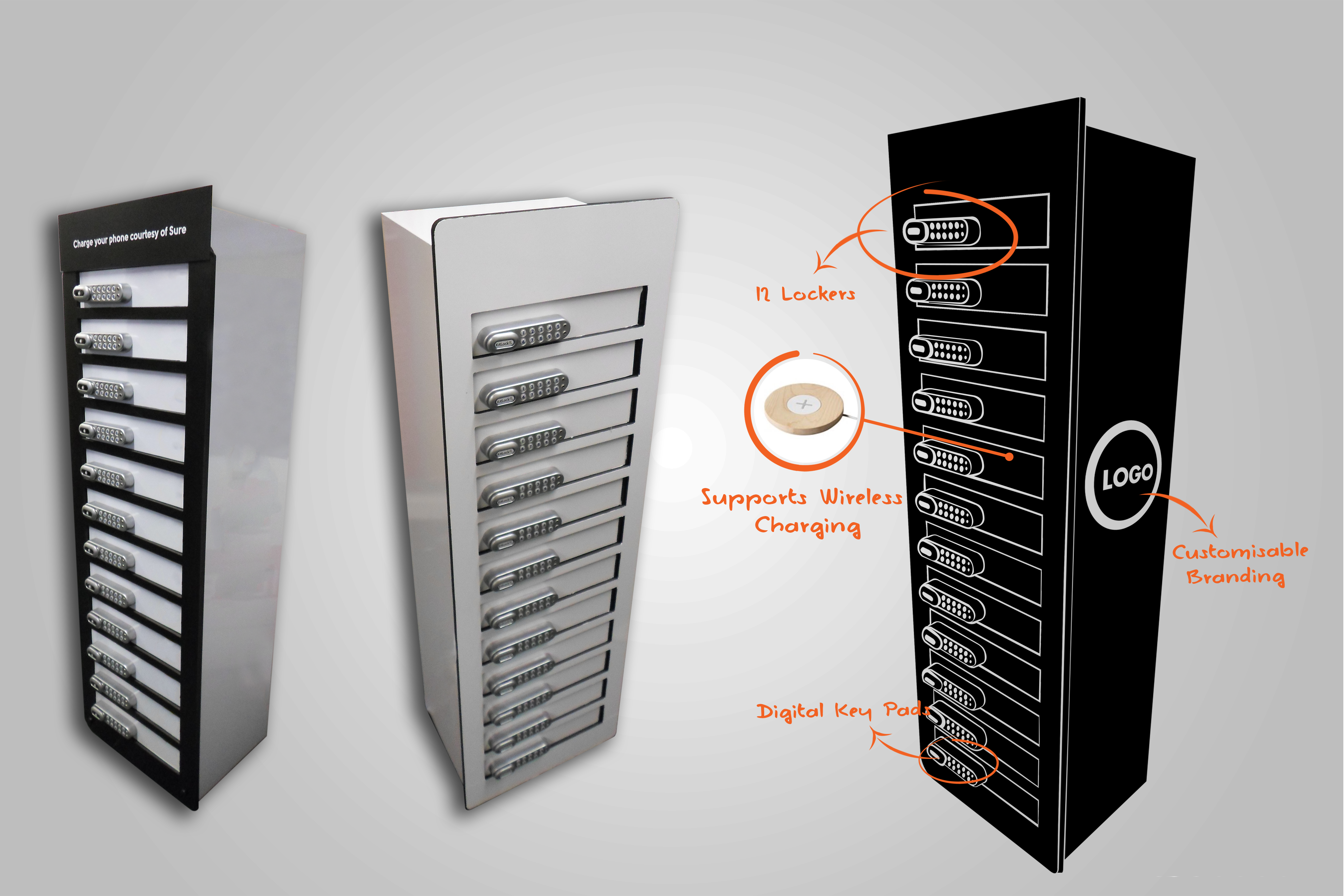
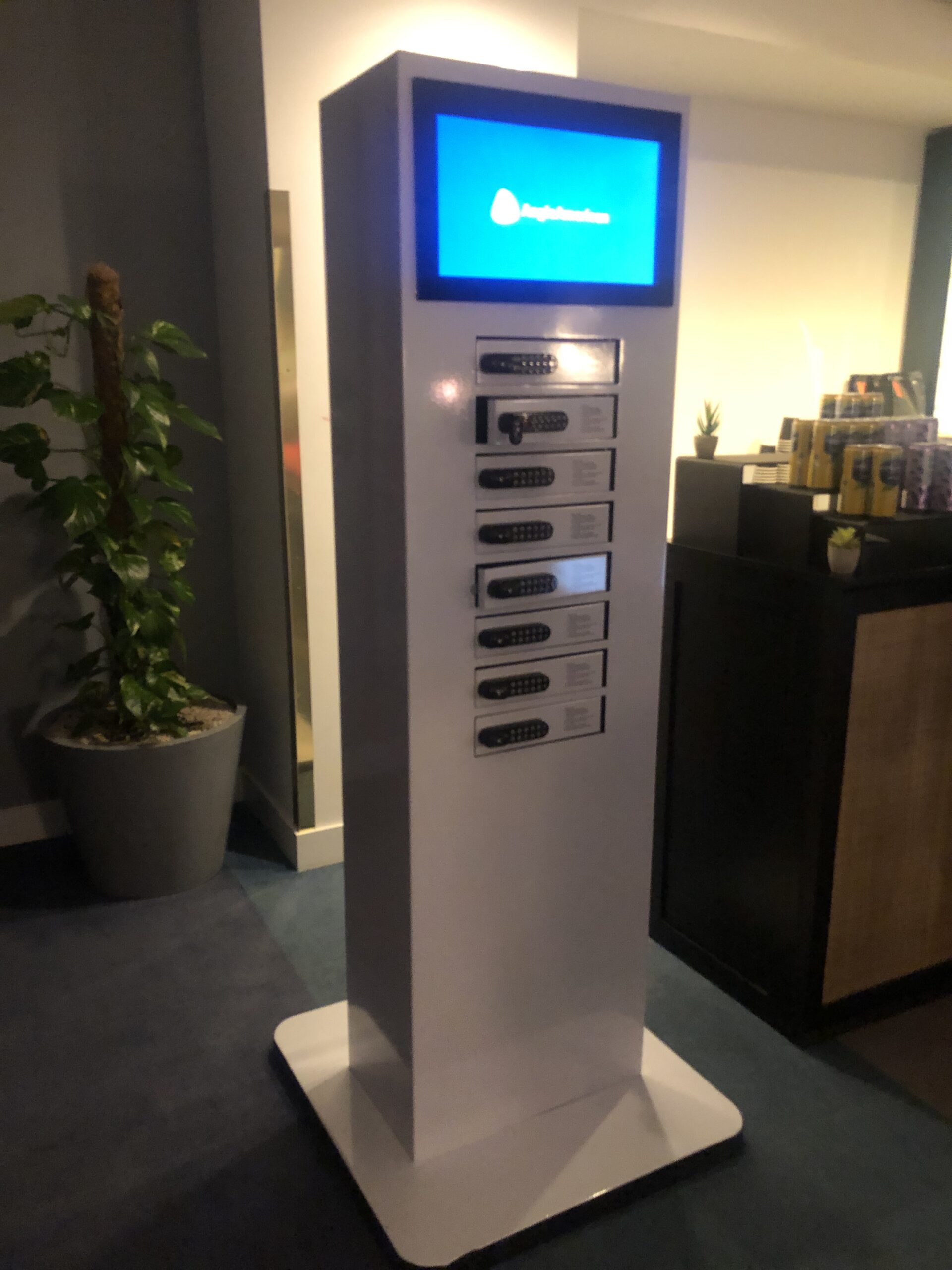
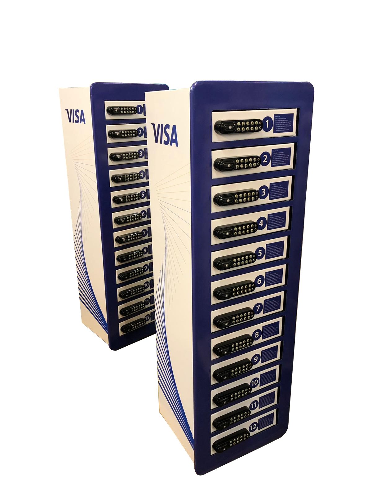
Our smartphones have become extensions of ourselves, central to our personal and professional lives. This dependence has fueled the demand for reliable on-the-go phone charging lockers. In response, phone charging lockers have become a ubiquitous and essential amenity in a vast array of public and private venues. From the high-traffic corridors of international airports and the bustling floors of trade show conventions to the quiet study halls of university campuses and the vibrant atriums of shopping malls, these lockers provide a secure and convenient haven for devices in need of power. By offering a safe place to charge, venues can significantly enhance visitor experience, increase dwell time, and drive engagement. Vischarge, a prominent provider in this burgeoning market, offers a diverse portfolio of charging solutions tailored to various needs. Their product line includes traditional lockable lockers, open-bay non-locker stations, and advanced models featuring interactive LCD screens with PIN code access or seamless wireless charging capabilities. This guide is conceived as a deep, technically informed, and eminently practical resource for the ecosystem of professionals who own, operate, and manage these critical infrastructure assets. It is intended for service technicians on the front lines of maintenance, facility managers responsible for operational uptime, and business owners seeking to maximize their return on investment. The guide will meticulously walk through every facet of charging locker stewardship, from routine preventive care and scheduled maintenance to complex component replacement, systematic troubleshooting, and strategic upgrades. We will delve into the intricacies of charging cables, power electronics, and access control systems, providing clear, actionable guidance. The primary, overarching objective of this document is to empower operators to ensure the unwavering reliability, maximum uptime, and absolute safety of their charging locker systems. By adhering to the principles and practices outlined herein, operators can expect to see a tangible reduction in operational costs, a significant decrease in user-reported issues, and a corresponding increase in user trust and satisfaction.
Phone charging lockers
Anatomy of a Charging Locker System
A phone charging locker system which is also called a lockable phone charging station is a sophisticated assembly of components working in concert to provide secure and reliable charging for mobile devices. Understanding the anatomy of these systems is the first step towards effective maintenance and troubleshooting. While specific designs may vary, most charging lockers share a common set of core components.
Basic Components Overview
A typical phone charging locker system is a complex integration of various specialized components, each playing a vital role in its overall functionality and user experience. Understanding these individual parts and their interdependencies is fundamental for effective maintenance and troubleshooting. The core components generally include:
•Phone Charging Cables, Mats, or Wireless Coils: These are the direct interface with the user’s device and, consequently, the most frequently handled and thus most susceptible to wear and tear. They encompass a diverse array of connectors to ensure compatibility with the vast majority of mobile devices, including Apple’s proprietary Lightning, the increasingly ubiquitous USB-C (known for its reversible design and high power delivery capabilities), and the legacy Micro-USB. Beyond physical connections, many modern lockers also integrate wireless charging mats or inductive coils, offering a cable-free charging experience based on the Qi standard.
•Power Supply Unit (PSU), Transformers, and DC Regulators: The PSU serves as the critical power conversion hub of the charging locker. It efficiently converts the incoming alternating current (AC) from a standard wall outlet into the stable direct current (DC) required by mobile devices. This unit often incorporates step-down transformers to reduce voltage and sophisticated DC regulators to ensure a consistent, clean, and safe power output, protecting connected devices from voltage fluctuations and surges.
•Main Control Board (Motherboard/Embedded Controller): Often referred to as the ‘brain’ of the system, the main control board is an embedded computer that orchestrates all primary functions. This includes intelligent power distribution to individual bays, management of various charging protocols, control over the access and locking mechanisms, and processing user interface inputs. It typically houses a microcontroller or processor, memory, and communication interfaces essential for its operation.
•Batteries (if backup or integrated): While many phone charging lockers operate solely on grid power, some advanced or specialized models incorporate internal batteries. These can serve as an uninterruptible power supply (UPS) for backup during power outages, enabling continued service. In other designs, particularly portable units, batteries provide the primary power source. Certain individual locker keypads or access systems may also rely on smaller, dedicated batteries (e.g., AAA cells) for their operation. These batteries necessitate regular monitoring and, eventually, replacement to ensure system reliability and safety.
•Enclosure, Ventilation, Cooling, and Mechanical Structure: The enclosure provides the physical housing, security, and aesthetic appeal of the charging locker. Constructed from durable materials such as steel, aluminum, or high-impact plastics, it protects internal components from environmental factors and tampering. Integrated ventilation systems, often comprising fans and strategically placed vents, are crucial for dissipating the heat generated during the charging process, preventing thermal damage to electronics. The mechanical structure ensures stability, durability, and secure mounting.
•Access and Locking Systems: These mechanisms are paramount for securing the contents of the locker bays and managing user access. They can range from digital PIN keypads, which allow users to set temporary codes, to electromechanical locks controlled by the main board, and advanced RFID (Radio-Frequency Identification) or smart card readers that integrate with existing access credentials. Traditional key locks are also found in simpler or older models. The selection of an access system is typically driven by security requirements, user convenience, and integration needs.
•Wiring Harnesses, Connectors, and Sensors: An intricate network of wiring harnesses and specialized connectors meticulously links all the aforementioned components, facilitating power and data transfer. Various sensors are integrated throughout the system to provide critical feedback to the control board and users. These can include door sensors (to detect open/closed status), occupancy sensors (to determine if a device is present), and status LEDs (to indicate charging progress or errors).
Interactions Between Subsystems and Common Architectures
The phone charging locker motherboard serves as the central command unit, meticulously coordinating the complex interactions between all the various subsystems. This orchestration is critical for seamless operation. For instance, when a user inputs a PIN code or presents an RFID card, the access control system (be it a keypad or reader) communicates this input to the motherboard. The motherboard then processes this information, verifies the credentials against its internal database or a connected network, and, upon successful authentication, sends a command to the electromechanical lock of the designated locker bay to release. Concurrently, the motherboard initiates the charging process, actively monitoring the power flow to the device and its charging status. In more advanced systems, this monitoring can include real-time data on voltage, current, and even the health of the connected device’s battery, feeding this information back to a user interface or a remote management system.
Communication between these subsystems often occurs via standardized protocols, such as I2C, SPI, or UART, ensuring efficient and reliable data exchange. The architectural design of modern charging locker systems increasingly emphasizes modularity. This modular approach is a significant advantage, as it allows for easier maintenance, quicker troubleshooting, and more straightforward upgrades. For example, if an individual charging module or an access control keypad fails, it can often be replaced as a standalone unit without necessitating the replacement of the entire system or extensive re-wiring. This reduces repair times and costs, making the system more resilient and adaptable.
We exemplify this commitment to robust and adaptable design. They offer a diverse array of phone charging locker configurations, including models with sophisticated PIN or RFID access, specifically engineered to cater to the varied requirements of different venues and user demographics. Their systems are meticulously designed with a strong emphasis on durability, featuring robust construction materials and user-friendly interfaces that simplify both operation and maintenance. A thorough understanding of the specific architecture of your particular charging locker system is not merely beneficial but absolutely crucial for effective maintenance and proactive troubleshooting. It is always imperative to consult the manufacturer’s documentation for detailed schematics, component breakdowns, and interaction protocols specific to your system, as this will provide the most accurate and comprehensive information for any service or upgrade procedures.
Preventive Maintenance Practices for Phone charging Lockers
Proactive preventive maintenance is paramount to ensuring the longevity, reliability, and optimal performance of phone charging locker systems. By establishing a structured maintenance regimen, operators can significantly reduce the incidence of unexpected failures, minimize downtime, and extend the operational lifespan of their equipment. This section outlines key preventive maintenance practices, encompassing routine inspections, cleaning, environmental considerations, software updates, and inventory planning.
Establishing a Maintenance Schedule
A well-defined and rigorously followed maintenance schedule is the cornerstone of effective preventive care. The frequency and depth of maintenance tasks must be meticulously tailored to the specific operational context, considering factors such as the usage intensity of the charging lockers, the environmental conditions in which they operate, and the manufacturer’s recommendations. A tiered approach, systematically incorporating daily, weekly, monthly, quarterly, and yearly checks, is highly recommended to comprehensively cover all critical aspects of the system and ensure no potential issues are overlooked.
•Daily Checks: These are typically quick, visual inspections performed by on-site staff. The primary focus is on identifying immediate user-facing issues and obvious physical damage. This includes verifying that all locker bays appear functional, checking for any visible signs of tampering or vandalism, and ensuring that all charging cables are present, appear intact, and are correctly positioned within their bays. Any visible debris, spills, or foreign objects should be promptly and safely removed. This daily vigilance helps maintain a clean and inviting appearance while catching minor issues before they escalate.
•Weekly Checks: Building upon the daily routine, weekly checks involve a more thorough cleaning of all external surfaces to remove grime and fingerprints. Special attention should be paid to ventilation grilles, ensuring they are free from dust and obstructions that could impede airflow. A sample of locker doors should be opened and closed to confirm smooth operation, and a few charging ports should be tested with a known working device to verify basic functionality. This routine helps prevent accumulation of dirt and ensures mechanical components remain operational.
•Monthly Checks: Monthly maintenance is more detailed and technical. It involves a comprehensive inspection of all user-facing components, particularly charging cables and connectors, for any signs of wear, fraying, cuts, or loose connections. Charging contacts and mats should be cleaned with appropriate non-abrasive solutions to ensure optimal conductivity. The functionality of all locking mechanisms—PIN keypads, RFID readers, and traditional key locks—must be verified for each bay. Display screens should be checked for clarity, responsiveness, and any dead pixels. If the system supports error logging, these logs should be reviewed for recurring issues or anomalies that might indicate underlying problems.
•Quarterly Checks: These checks delve deeper into the electrical and structural integrity of the locker. Comprehensive electrical checks should be performed, including verifying the stability of the power supply unit (PSU) output and inspecting all fuses and circuit breakers for proper rating and condition. Internal components should undergo thorough cleaning using compressed air to remove dust from circuit boards and cooling fans, ensuring proper ventilation and preventing overheating. The structural integrity of the entire locker unit should be assessed, with any loose fasteners or mounting hardware tightened to prevent vibration-induced damage. Firmware and software should be reviewed for available updates, which should be applied according to manufacturer guidelines to ensure security and optimal performance.
•Yearly Checks: The yearly check is the most extensive, often requiring specialized tools and expertise, and may involve professional service. It includes a detailed internal inspection of the motherboard and power electronics for signs of wear, corrosion, or impending failure. Access control systems should be calibrated to ensure accuracy and responsiveness. A complete review of usage data and error trends from the past year is crucial for anticipating future issues and planning proactive component replacements. If the locker system includes batteries, their health should be thoroughly assessed, and replacements planned based on their expected lifespan and performance degradation.
Maintaining a detailed and accessible record of all maintenance activities is not merely good practice; it is crucial for effective asset management. This documentation should include dates of service, tasks performed, any issues identified and their resolutions, and the parts replaced. Such meticulous record-keeping aids significantly in troubleshooting persistent problems, identifies patterns of recurring failures, supports warranty claims, and provides valuable data for future maintenance planning and budgeting.
Routine Inspections: Cables, Connectors, Ventilation, Locks, Display, Electronics
Regular inspections are critical for identifying potential issues before they escalate into major problems. Each component requires specific attention:
•Cables and Connectors: These are often the most abused parts of a charging locker. Inspect for fraying, cuts, bends, or discoloration. Ensure connectors fit snugly into ports and are not loose or bent. The integrity of strain relief mechanisms at the cable-connector junction is particularly important. [1]
•Ventilation: Check all air intake and exhaust vents for dust accumulation or obstructions. Blocked vents can lead to overheating, which can damage internal electronics and shorten component lifespan. Ensure any cooling fans are operating quietly and efficiently.
•Locks: For PIN keypads, check for worn buttons or unresponsive keys. For RFID readers, ensure the reading surface is clean and free from scratches. Mechanical key locks should operate smoothly without sticking. Test the locking and unlocking mechanism of each bay to confirm proper function and security.
•Display Screens: Inspect LCD or LED displays for dead pixels, flickering, or unresponsiveness. Ensure touchscreens are calibrated and accurate.
•Electronics: While typically enclosed, listen for unusual noises (e.g., buzzing from power supplies) and check for any unusual odors (e.g., burning electronics). For systems with accessible internal components, visually inspect circuit boards for signs of overheating, such as discolored components or bulging capacitors.
Cleaning Procedures (Cable Cleaning, Contacts, Mats, Lockers)
Cleanliness directly impacts performance and longevity. Different components require specific cleaning methods:
•Locker Exterior: Regularly wipe down all external surfaces with a mild detergent solution and a soft, non-abrasive cloth. Avoid harsh chemicals or abrasive cleaners that can damage finishes. For powder-coated surfaces, a damp cloth is usually sufficient.
•Charging Cables and Contacts: Disconnect cables from both the locker and any devices. Gently wipe down the cable sheathing with a damp microfiber cloth. For charging contacts (e.g., inside USB ports), use a dry, soft brush or compressed air to remove dust and lint. A cotton swab lightly dampened with isopropyl alcohol can be used for stubborn grime on metal contacts, ensuring the alcohol evaporates completely before re-use.
•Charging Mats/Wireless Coils: If present, clean the surface of wireless charging mats with a soft, damp cloth. Ensure no liquids seep into the unit. For internal wireless coils, ensure they are free from dust and debris.
•Internal Components: With power disconnected, use compressed air to gently remove dust from circuit boards, power supplies, and cooling fans. Avoid direct contact with electronic components.
Environmental Checks: Temperature, Humidity, Dust, Vibration
Environmental factors play a significant role in the health of electronic equipment. Charging lockers should ideally be installed in a well-ventilated indoor area.
•Temperature: Excessive heat is a major enemy of electronics. Ensure the operating environment stays within the manufacturer’s recommended temperature range. Monitor for signs of overheating within the locker, such as unusually warm surfaces or frequent fan operation. Proper ventilation is key to heat dissipation.
•Humidity: High humidity can lead to condensation and corrosion of electronic components, while extremely low humidity can increase static electricity risks. Maintain a moderate humidity level in the operating environment.
•Dust: Dust acts as an insulator, trapping heat and potentially causing short circuits. Regular cleaning of vents and internal components helps mitigate dust buildup.
•Vibration: Excessive vibration can loosen electrical connections and damage delicate components. Ensure the locker is securely anchored to a stable surface (wall and/or floor) to prevent movement and vibration.
Firmware / Software Updates (if controllers support them)
Many modern charging locker systems are equipped with embedded controllers that run firmware or software. Regular updates are crucial for:
•Bug Fixes: Addressing known issues that can affect performance or security.
•Security Patches: Protecting the system from vulnerabilities and cyber threats.
•New Features: Enhancing functionality, improving charging efficiency, or adding new access control options.
•Compatibility: Ensuring compatibility with newer device charging protocols or accessories.
Always follow the manufacturer’s instructions for firmware updates, as incorrect procedures can brick the device. Back up existing configurations before performing updates.
Logging and Monitoring (Error Logs, Usage Counters, Access Events)
Advanced charging locker systems often include logging and monitoring capabilities. Regularly reviewing this data can provide valuable insights into system health and usage patterns:
•Error Logs: These logs record system malfunctions, such as charging failures, lock errors, or power supply issues. Analyzing error trends can help diagnose intermittent problems and predict component failures.
•Usage Counters: Tracking the number of charging cycles or locker uses can help determine component wear rates and inform preventive replacement schedules, especially for high-wear items like cables and locks.
•Access Events: Logs of access attempts (successful and unsuccessful) can help monitor security, identify potential misuse, and assist in resolving user disputes (e.g., forgotten PINs).
Spare Parts Inventory Planning
Maintaining a strategic inventory of spare parts is essential for rapid repairs and minimizing downtime. Based on usage patterns and component wear rates, prioritize stocking consumables and high-failure-rate items. Key spare parts often include:
•Phone Charging Cables: A variety of types (Lightning, USB-C, Micro-USB) and quantities, as these are the most frequently replaced items. Consider sourcing quality cables with robust strain relief.
•Locking Mechanisms: Spare PIN keypads, RFID readers, or mechanical lock cylinders, depending on the system.
•Power Supply Units: A spare PSU can quickly resolve power-related issues.
•Fuses: Essential for protecting electrical circuits.
•Small Hardware: Screws, zip ties, and other fasteners for reassembly and cable management.
For critical components like motherboards, consider having a spare on hand or establishing a rapid replacement agreement with the manufacturer or supplier.
By diligently implementing these preventive maintenance practices, operators can ensure their phone charging locker systems remain reliable, secure, and ready to serve users effectively for years to come.
Phone Cable & Charging Mat / Wireless Coil Maintenance & Replacement for Phone Charging Lockers
Charging cables, mats, and wireless coils are the primary interface between the locker and the user’s device, making them highly susceptible to wear, damage, and obsolescence. Their proper maintenance and timely replacement are crucial for ensuring continuous service and user satisfaction.
Common Cable Types Used in Locker Systems
Phone charging lockers typically accommodate a variety of mobile devices, necessitating a range of cable types. The most common include:
•Lightning: Primarily for Apple iPhones and iPads.
•USB-C: The increasingly universal standard for newer Android devices, laptops, and other electronics, known for its reversible connector and high power delivery capabilities.
•Micro USB: Still prevalent in older Android devices, power banks, and various accessories.
•Proprietary Multi-Cable Harnesses: Some locker systems may use integrated multi-tip cables to offer broader compatibility with a single physical connection.
Charging Mats or Wireless Induction Pads (if used)
Wireless charging, based on inductive power transfer, offers convenience by eliminating physical cable connections. These systems typically involve a charging mat or coil embedded within the locker bay. While less prone to physical wear than cables, they can still experience issues related to misalignment, foreign objects, or electronic failure.
Symptoms of Cable / Mat Failure
Recognizing the signs of impending or actual cable/mat failure is key to proactive maintenance. Common symptoms include:
•Intermittent Charging: The device connects and disconnects from charging without being moved.
•No Charging Response: The device does not register a charge when connected, or the charging indicator on the locker or device does not activate.
•Slow Charging: Charging takes significantly longer than usual, indicating reduced power delivery.
•Loose Connection: The cable connector wiggles excessively in the device’s port or the locker’s charging module, often requiring manual support to maintain a connection .
•Physical Damage: Visible signs of wear such as frayed insulation, exposed wires, bent or broken connectors, or discoloration (especially near the connector) .
•Overheating: The cable or connector becomes unusually hot during charging, which can be a safety hazard and indicates internal damage or excessive resistance .
•Error Messages: Some smart lockers or devices may display specific error codes related to charging issues.
For wireless charging mats, symptoms might include:
•No Wireless Charging: Device placed on the mat does not begin charging.
•Intermittent Wireless Charging: Charging starts and stops randomly.
•Error Lights: Indicator lights on the mat or locker show an error state.
•Overheating: The mat or device becomes excessively hot during wireless charging.
Testing Methods
To accurately diagnose cable and mat issues, various testing methods can be employed:
•Visual Inspection: The simplest and often most effective first step. Look for any of the physical damage symptoms mentioned above.
•Multimeter: A multimeter can be used to check for continuity (to detect breaks in the wire) and voltage drop across the cable. A significant voltage drop under load indicates excessive resistance, often due to internal wire damage.
•USB Power Meters: These inline devices measure the voltage and current flowing through a USB cable, providing real-time data on charging performance. They can help identify if a cable is delivering insufficient power or current.
•Load Tests: Connect a known working device or a dedicated USB load tester to the cable to simulate real-world charging conditions and observe performance.
•Swapping: Test the suspected faulty cable with a known good cable, or vice-versa, to isolate whether the issue lies with the cable, the device, or the locker’s charging module.
For wireless charging mats, ensure the device is properly aligned, free of thick cases, and that the mat itself is receiving power. Testing involves using a compatible device and observing the charging status.
Safe Procedures for Removal and Replacement
When replacing cables or components, safety is paramount:
1.Disconnect Power: Always unplug the entire charging locker from the wall outlet before performing any maintenance or replacement .
2.Access Electronics: Unlock and open the rear access panel or door to expose the charging modules and wiring [5].
3.Document Existing Setup: Take photos of the cable routing and zip tie placement. This will serve as a valuable reference during reassembly.
4.Disconnect Old Cables: Carefully unplug the charging cables from their respective charging modules. If zip ties secure the cables, use wire cutters or scissors to remove them.
5.Remove Old Cables: Slide the old cables out through the cable holes into the charging lockers.
6.Install New Cables: Plug the replacement cables into the charging modules. Secure them with new zip ties, following the original routing. Route the cables through the cable holes into the charging lockers.
7.Test Functionality: Before closing the locker, plug it back into power and test each new cable with a device to ensure proper charging.
8.Secure and Reassemble: Once confirmed working, unplug the locker again, close and secure all access panels, and re-anchor the unit if it was moved.
Sourcing Quality Replacement Cables & Mats
Investing in high-quality replacement components is crucial for durability and performance. Consider the following specifications:
•Current Rating (Amperage): Ensure the replacement cables can handle the current required for fast charging (e.g., 2A, 3A, 5A). Underrated cables can overheat and fail prematurely.
•AWG (American Wire Gauge): Lower AWG numbers indicate thicker wires, which generally offer better power delivery and durability. For charging, lower AWG (e.g., 24AWG for power lines) is preferable.
•Shielding: Good shielding protects against electromagnetic interference and contributes to cable integrity.
•Durability: Look for cables with reinforced connectors, braided nylon sheathing, or robust strain relief to withstand frequent use and bending [1].
•Certification: Opt for cables certified by relevant standards bodies (e.g., MFi for Apple Lightning cables, USB-IF for USB-C cables).
For wireless charging mats, ensure replacements are compatible with the locker’s power delivery system and meet safety standards.
Cable Routing, Strain Relief, Connector Retention Best Practices
Proper cable management significantly extends cable life and prevents damage:
•Strain Relief: Ensure cables have adequate strain relief at both the locker’s charging module connection and the user-facing end. This prevents stress on the internal wires when cables are pulled or bent.
•Secure Routing: Use zip ties or cable clips to neatly route cables within the locker, preventing tangles and accidental disconnections. Avoid sharp bends or kinks.
•Connector Retention: Design or select lockers where the user-facing cable connectors are securely retained within the bay, preventing them from being pulled out completely or excessively stressed.
•Length Management: Provide just enough cable length for comfortable use within the locker bay, avoiding excessive slack that can lead to tangles or damage.
Cable Life Expectancy and Proactive Replacement Criteria
The lifespan of charging cables in public charging lockers is inherently limited due to frequent and sometimes rough handling. While a typical high-quality cable might withstand thousands of bends, the reality of public use often shortens this significantly. Proactive replacement criteria should be established:
•Usage-Based: If the locker system tracks usage, consider replacing cables after a certain number of charging cycles or a set period (e.g., every 6-12 months) regardless of visible damage.
•Condition-Based: Replace cables immediately upon observing any of the failure symptoms mentioned above, especially physical damage or inconsistent charging.
•Manufacturer Recommendations: Adhere to any replacement guidelines provided by the locker or cable manufacturer.
Integration of Vischarge’s “Lifetime Cable Replacement” Feature
Vischarge, a notable provider of phone charging solutions, offers a compelling
feature: “Lifetime Cable Replacement on all Vischarge® Phone Charging Solutions!” . This feature significantly reduces the long-term maintenance burden and cost associated with cable replacement for operators using Vischarge products. It underscores the importance of durable, high-quality cables and a commitment to sustained functionality, making Vischarge an attractive option for venues seeking to minimize operational overhead related to cable wear and tear.
Lockable phone charging station
Power Electronics & Motherboard Maintenance / Upgrades
The power electronics and motherboard form the central nervous system of a phone charging locker, orchestrating power delivery, charging protocols, access control, and user interface interactions. Their reliable operation is critical for the overall functionality and safety of the system. Maintenance in this area often involves diagnostics, safe handling, and potential upgrades.
Role of the Motherboard (Controller Board) in Managing Charging, Monitoring, Access, User Interface
The motherboard, or controller board, is an embedded system responsible for a multitude of functions within the charging locker. Its primary roles include:
•Charging Management: Regulating voltage and current to individual charging ports, implementing fast-charging protocols, and protecting against overcharge, overcurrent, and short circuits.
•Monitoring: Collecting data on charging status, locker occupancy (via IR sensors), and system health. This data can be logged for troubleshooting and usage analysis.
•Access Control: Interfacing with PIN keypads, RFID readers, or other locking mechanisms to grant or deny access to individual locker bays. It processes user inputs and controls electromechanical locks.
•User Interface: Driving LCD screens or LED indicators to display charging status, locker availability, and user instructions.
•Communication: In networked systems, the motherboard facilitates communication with a central management system (e.g., via Ethernet or Wi-Fi) for remote monitoring, diagnostics, and firmware updates.
Key Components: Processors / Microcontrollers, Power Staging Circuitry, Protection (Fuses, Current Limiters, Overvoltage Protection)
Inside the motherboard and associated power electronics, several key components ensure safe and efficient operation:
•Processors / Microcontrollers: These are the computational core, executing the firmware that governs all locker functions. They interpret commands, manage data flow, and control peripheral devices.
•Power Staging Circuitry: This includes components like DC-DC converters, voltage regulators, and power MOSFETs that efficiently convert and distribute power from the main power supply to the individual charging modules and other internal components.
•Protection Circuitry: Essential for safety and longevity, this includes:
•Fuses: Overcurrent protection devices that break a circuit if current exceeds a safe level.
•Current Limiters: Prevent excessive current draw by individual devices, protecting both the device and the locker’s power supply.
•Overvoltage Protection (OVP): Safeguards components from damage due to voltage spikes or surges.
•Thermal Protection: Sensors and control logic to prevent overheating of components, often by reducing power or activating cooling fans.
Diagnosing Motherboard Problems (Symptoms: No Power, Erratic Behavior, LED / Display Failure)
Diagnosing issues with the motherboard or power electronics often requires a systematic approach. Common symptoms include:
•No Power to Unit/Bays: If the entire locker or multiple bays are unresponsive, the issue could stem from the main power supply unit (PSU), main fuse, or the motherboard’s power input section. Check the main power connection and fuses first.
•Erratic Behavior: Unpredictable operation, such as lockers opening randomly, charging starting/stopping without command, or unresponsive controls, often points to a software glitch or a faulty microcontroller on the motherboard.
•LED / Display Failure: If status LEDs are off or flickering, or the LCD screen is blank or displaying garbled text, it could indicate a problem with the motherboard’s display driver, power supply to the display, or the display unit itself.
•Charging Failures (Multiple Bays): If several bays fail to charge simultaneously, but the locker’s other functions are operational, it might indicate an issue with the power distribution circuitry on the motherboard or a shared charging module.
•Unusual Odors or Sounds: A burning smell or unusual buzzing/clicking sounds from within the locker are strong indicators of electrical component failure and require immediate power disconnection and inspection.
Safe Removal, Repair, or Replacement of Controller Boards
Working with internal electronics requires caution and adherence to safety protocols:
1.Disconnect All Power: Absolutely critical. Unplug the locker from the mains and, if applicable, disconnect any internal backup batteries.
2.Discharge Capacitors: Large capacitors on power supply boards can store significant charge even after power is disconnected. Allow sufficient time for them to discharge or safely discharge them using appropriate tools.
3.Electrostatic Discharge (ESD) Precautions: Wear an ESD wrist strap and work on an ESD-safe mat to prevent damage to sensitive electronic components. Avoid touching circuit board components directly.
4.Documentation: Take clear photos of all cable connections and component placements before disassembly. Label cables if necessary.
5.Gentle Handling: Motherboards and other circuit boards are fragile. Handle them by their edges and avoid bending or applying excessive force.
6.Component Replacement: For board-level repairs (e.g., replacing a faulty capacitor or fuse), specialized soldering skills and equipment are often required. For most field technicians, replacing the entire controller board is a more practical and reliable solution.
7.Reassembly and Testing: Reconnect all components carefully, ensuring proper seating of connectors. Before closing the locker, perform initial power-up tests to confirm functionality.
Firmware and Software Versioning, Backup, and Rollback
Managing firmware is an important aspect of motherboard maintenance:
•Versioning: Keep track of the firmware version running on each locker. This is crucial for compatibility with management software and for troubleshooting.
•Backup: If the system allows, back up the current firmware and configuration settings before performing any updates. This provides a recovery point.
•Rollback: Ensure there is a procedure to revert to a previous stable firmware version if an update introduces new issues. Always follow manufacturer guidelines for updates.
Upgrading Boards for New Features (e.g. Faster Charge, Better Efficiency, Added Access Modes)
Technology evolves rapidly, and older charging lockers may benefit from motherboard upgrades to incorporate new features:
•Faster Charging Protocols: Upgrading to a board that supports newer fast-charging standards (e.g., USB Power Delivery, Quick Charge) can significantly improve user experience.
•Improved Efficiency: Newer boards often feature more efficient power management ICs, reducing energy consumption and heat generation.
•Added Access Modes: Upgrades can enable support for new access technologies like biometric scanners, QR code readers, or enhanced RFID systems.
•IoT / Remote Monitoring: Boards with integrated network connectivity can enable remote diagnostics, usage tracking, and predictive maintenance capabilities.
Consult with the manufacturer or a qualified service provider to determine upgrade compatibility and procedures.
Heat Dissipation, Cooling, and Reliability Considerations (Capacitor Life, Thermal Cycling)
Effective thermal management is paramount for the long-term reliability of power electronics and motherboards. Overheating can drastically shorten the lifespan of components, particularly electrolytic capacitors, which are sensitive to temperature.
•Ventilation: Ensure internal and external airflow paths are clear and unobstructed. Regular cleaning of fans and vents is essential.
•Cooling Fans: Verify that any cooling fans are operational and free from dust buildup. Replace noisy or failing fans promptly.
•Component Spacing: Proper spacing of heat-generating components on the PCB and within the enclosure helps dissipate heat.
•Thermal Cycling: Repeated heating and cooling cycles can stress solder joints and components. Maintaining stable operating temperatures minimizes this stress.
•Capacitor Life: Electrolytic capacitors have a finite lifespan that is highly dependent on temperature. Operating at lower temperatures can significantly extend their life, reducing the likelihood of power supply instability or failure.
Board-Level Diagnostics (Oscilloscope, Logic Analyzer, Signal Path Tracing)
For advanced troubleshooting and repair, specialized tools and techniques may be employed:
•Oscilloscope: Used to visualize electrical signals and waveforms, helping to diagnose issues with power supply ripple, signal integrity, and timing problems.
•Logic Analyzer: Useful for debugging digital circuits, verifying communication protocols (e.g., I2C, SPI, UART) between components on the board.
•Signal Path Tracing: Involves systematically following the electrical path of signals and power through the circuit board using schematics and multimeters to pinpoint faulty components.
These advanced diagnostics are typically performed by experienced electronics technicians or engineers.
Battery Replacement & Management (if applicable)
While many phone charging lockers operate solely on mains power, some models incorporate internal batteries for backup power, portability, or as an integrated feature in battery-powered locker units. Effective battery management is crucial for safety, reliability, and maximizing the lifespan of these systems.
Situations Where Batteries Are Included
Batteries are typically found in phone charging lockers in the following scenarios:
•Backup Power: To ensure continued operation and charging during power outages, providing uninterrupted service.
•Integrated Battery Lockers: Some designs feature individual locker bays with their own integrated, rechargeable batteries, offering a truly portable charging solution within the locker itself.
•Digital Keypads/Access Systems: As seen with some ChargeTech models, individual locker keypads may require AAA batteries for initial setup or ongoing operation, separate from the main charging power.
Battery Types Commonly Used
The type of battery used depends on the application and power requirements. Common types include:
•Lithium-Ion (Li-ion) / Lithium-Polymer (Li-poly): These are widely used for their high energy density, light weight, and rechargeable nature. They are common in integrated battery locker systems and larger backup power units.
•Sealed Lead-Acid (SLA): Often found in larger, stationary backup power systems due to their robustness and cost-effectiveness, though they are heavier and have lower energy density than lithium-ion.
•Alkaline (e.g., AAA): Used for low-power applications like digital keypads
Monitoring Battery Health (Voltage, Capacity, Internal Resistance)
Regular monitoring of battery health is essential to predict failures and ensure optimal performance:
•Voltage: Check the open-circuit voltage and voltage under load. A significant drop under load can indicate a weakening battery.
•Capacity: Over time, a battery’s ability to hold a charge (its capacity) diminishes. Advanced systems may track this electronically. For simpler systems, observing how long a battery holds a charge under typical use can indicate degradation.
•Internal Resistance: An increase in internal resistance is a key indicator of battery aging and degradation, leading to reduced performance and increased heat generation. Specialized battery testers can measure this.
Safe Removal and Replacement: Mechanical and Electrical Safety, Matching Spec, Balancing, Calibration
Battery replacement must be performed with extreme care to ensure safety and proper functionality:
1.Safety First: Always disconnect the main power to the locker. Wear appropriate personal protective equipment (PPE), including insulated gloves and eye protection, especially when handling larger battery packs.
2.Mechanical Safety: Ensure the locker is stable and secure. Use proper tools to access battery compartments, avoiding damage to wiring or other components.
3.Electrical Safety: Avoid short-circuiting battery terminals. Work in a dry environment. For multi-cell battery packs, be aware of the total voltage.
4.Matching Specifications: Always replace batteries with units that precisely match the original specifications (voltage, capacity, chemistry, and physical dimensions). Using incompatible batteries can lead to performance issues, damage, or safety hazards.
5.Balancing (for multi-cell packs): If replacing individual cells within a multi-cell lithium-ion pack, ensure the new cells are balanced with existing ones to prevent overcharging or over-discharging of individual cells, which can lead to thermal runaway.
6.Calibration: After replacing batteries, some systems may require recalibration to accurately reflect the new battery’s state of charge and capacity. Refer to the manufacturer’s service manual for specific procedures.
Disposal, Recycling, and Regulatory Compliance
Batteries, especially lithium-ion and lead-acid, contain hazardous materials and must be disposed of responsibly. Adhere to all local, national, and international regulations for battery recycling and disposal. Never dispose of batteries in regular waste streams. Many manufacturers and retailers offer recycling programs.
Firmware / Control Updates Post-Replacement (Recalibration, Cell Matching)
After battery replacement, particularly for integrated battery systems, it may be necessary to:
•Recalibrate: Update the system’s firmware or control unit to recognize the new battery’s characteristics and recalibrate its state-of-charge algorithms.
•Cell Matching: For complex battery management systems (BMS) in multi-cell packs, firmware updates might be required to optimize cell matching and ensure uniform charging and discharging across the pack.
Always consult the manufacturer’s documentation for post-replacement procedures to ensure optimal battery performance and safety.
Access Control Systems: PIN Keypads, Key Locks & RFID / Smart Access
Access control systems are fundamental to the security and user experience of phone charging lockers. They dictate how users interact with the lockers to store and retrieve their devices. This section details the various types of access systems, their common failure modes, maintenance, and replacement procedures.
Overview of Access Methods and Trade-offs
Phone charging lockers employ several access methods, each with its own advantages and disadvantages:
•PIN Codes / Keypads:
•Pros: Cost-effective, no physical key/card required, customizable codes. Many systems allow users to set their own temporary PINs, which are then cleared after use [6].
•Cons: Users can forget PINs, keypads can wear out, susceptible to
shoulder surfing or brute-force attacks if not properly secured.
•Mechanical Key Locks / Cam Locks:
•Pros: Simple, robust, no power required, familiar to users.
•Cons: Keys can be lost, stolen, or duplicated; key management can be cumbersome for operators; no audit trail.
•RFID / NFC Smart Cards or Tokens:
•Pros: Fast, convenient, secure (when properly implemented), can be integrated with existing access control systems (e.g., employee badges, student IDs), provides an audit trail.
•Cons: Requires users to carry a card/token, readers can be expensive, potential for card loss or damage.
•Hybrid Systems: Combine elements, such as a PIN keypad with an RFID reader, offering flexibility and redundancy.
Common Failure Modes (Stuck Keys, Keypad Electrical Failure, Magnetization, Wear, Card Reader Failure)
Access control systems, being interactive components, are prone to various failure modes:
•PIN Keypads:
•Stuck/Unresponsive Keys: Due to dirt, debris, liquid ingress, or mechanical wear of the keypad membrane/buttons.
•Electrical Failure: Internal circuit board issues leading to complete keypad failure or intermittent operation.
•Worn Keypads: Repeated use can wear off numbers/symbols, making them difficult to read.
•Mechanical Key Locks:
•Stuck/Jammed Locks: Due to internal corrosion, foreign objects, or bent key pins.
•Broken Keys: Keys can break off inside the lock cylinder.
•Worn Mechanisms: Over time, the internal tumblers or cam can wear, leading to difficulty in locking/unlocking or complete failure.
•RFID / NFC Readers:
•Reader Failure: The reader unit may fail to detect cards/tokens due to internal electronic issues, damage to the antenna, or software glitches.
•Interference: Electromagnetic interference from other devices can disrupt reader operation.
•Physical Damage: Scratches or cracks on the reader surface can impair functionality.
Maintenance & Diagnostics (Voltage to Reader Circuits, Key Debounce, Scanning Signals)
Regular maintenance and diagnostic checks can prevent many common failures:
•Cleaning: Keep keypads, keyholes, and RFID reader surfaces clean and free of dust, dirt, and grime. Use appropriate cleaning solutions that won’t damage electronic components.
•Mechanical Checks: For key locks, lubricate moving parts with a suitable dry lubricant (e.g., graphite powder) to ensure smooth operation. Check for loose mounting screws.
•Electrical Checks:
•Voltage to Reader Circuits: Use a multimeter to verify that the correct voltage is being supplied to RFID readers and keypads. Incorrect voltage can cause erratic behavior or complete failure.
•Key Debounce: For keypads, erratic input or
multiple key presses from a single touch might indicate a debounce issue, which is typically a software/firmware problem or a failing switch matrix. * Scanning Signals: For RFID readers, specialized diagnostic tools can sometimes be used to check the strength and integrity of the scanning signal. However, for most field technicians, a simple test with a known working RFID card is sufficient.
Replacement of Keypad Modules, Key Switches, RFID Readers
When a component fails and cannot be repaired, replacement is necessary:
•Keypad Modules: Typically, the entire keypad module is replaced. Disconnect power, carefully detach the old module (often secured by screws or clips), disconnect its ribbon cable or wiring harness, and connect the new module. Ensure proper alignment and secure fastening.
•Key Switches (for mechanical locks): Replacing a key switch involves disassembling the lock mechanism, removing the old cylinder, and installing a new one. This often requires specialized tools and knowledge of lock mechanisms.
•RFID Readers: Disconnect power, remove the old reader, and connect the new one, ensuring all wiring (power, data) is correctly attached. Some RFID readers may require software configuration or pairing with the main control board after replacement.
Firmware / Security Aspects: Code Management, Encryption, Key Rollback
For electronic access systems, firmware and security are critical:
•Code Management: Implement robust procedures for managing PIN codes, especially master codes. Change default codes immediately upon installation. Regularly review and update access permissions.
•Encryption: Ensure that communication between the keypad/reader and the control board, and any stored access data, is encrypted to prevent unauthorized access or data breaches.
•Key Rollback: For RFID systems, have a mechanism to revoke lost or stolen RFID cards/tokens and issue new ones, ensuring the old credentials can no longer grant access.
Calibration, Registration of Cards, User Management
•Calibration: Some access systems, particularly touchscreens or sensitive keypads, may require periodic calibration to ensure accurate input.
•Registration of Cards: For RFID systems, a clear process for registering new RFID cards/tokens and associating them with specific locker access permissions is essential.
•User Management: Implement a system for managing user access, including adding new users, revoking access, and resetting forgotten PINs. This can be done via a local interface on the locker or through a remote management system.
Mechanical Alignment, Tamper Detection, and Protection
•Mechanical Alignment: Ensure that locker doors, hinges, and locking mechanisms are properly aligned. Misalignment can cause undue stress on locks, leading to premature wear or jamming.
•Tamper Detection: Advanced lockers may include sensors that detect forced entry or tampering attempts. These systems should trigger alarms or send alerts to facility managers.
•Protection: Physical protection against vandalism or damage to keypads and readers is important. Consider protective covers or recessed designs.
Integration, Testing & Troubleshooting
Effective integration, thorough testing, and systematic troubleshooting are vital for maintaining the operational integrity of phone charging locker systems. This section provides a framework for ensuring all components work harmoniously and for efficiently resolving issues when they arise.
End-to-End Testing Procedure: From User Interface to Actual Charging
An end-to-end testing procedure verifies the complete user experience and system functionality. This should be performed after any maintenance, repair, or upgrade:
1.User Interface Check: Verify that displays are clear, touchscreens are responsive, and all buttons (if present) function correctly.
2.Access Control Test: Test all access methods (PIN, RFID, key) for each locker bay. Ensure that correct credentials grant access and incorrect ones are denied.
3.Locker Door Mechanism: Confirm that doors open smoothly when unlocked and securely latch when closed.
4.Charging Cable/Mat Functionality: For each bay, connect a test device (e.g., a smartphone or tablet) to each available charging cable or place it on the wireless charging mat. Verify that the device begins charging and that the charging indicator (if any) illuminates.
5.Charging Performance: Use a USB power meter to confirm that the charging cables are delivering appropriate voltage and current to the test device.
6.Sensor Verification: If equipped, check door sensors (e.g., to confirm a locker is occupied) and other environmental sensors.
7.System Feedback: Observe if the system provides correct feedback (e.g.,
LED lights changing color, on-screen messages) for each action.
Test Scenarios (Correct PIN, Incorrect PIN, Card Read Failure, Door Open, Device Inserted/No Insert, Cable Fault)
To ensure robustness, test a variety of scenarios, including both normal operation and potential failure conditions:
•Correct PIN/Card: Verify that a valid PIN or RFID card successfully unlocks the designated locker.
•Incorrect PIN/Card: Ensure that an invalid PIN or RFID card is rejected and does not grant access. Check for any lockout mechanisms after multiple failed attempts.
•Card Read Failure: Simulate a card read failure (e.g., by holding the card at an awkward angle or too far from the reader) to see how the system responds.
•Door Open/Close: Test if the system correctly detects when a locker door is open or closed. For smart lockers, this might be used to indicate occupancy.
•Device Inserted/No Insert: If the system has device detection, verify that it correctly identifies when a device is connected for charging.
•Cable Fault: If possible, use a known faulty cable to test if the system can detect the fault and provide an appropriate error message or disable the port.
Use of Test Rigs, Diagnostic Jigs, Dummy Loads
For more advanced testing and diagnostics, specialized equipment can be invaluable:
•Test Rigs: A dedicated test rig can simulate various user inputs and environmental conditions, allowing for automated and repeatable testing of the locker’s control board and software.
•Diagnostic Jigs: These are custom-built tools that can quickly connect to the locker’s internal components (e.g., motherboard, charging modules) to run diagnostic tests and check for faults.
•Dummy Loads: An electronic dummy load can be used to simulate a device being charged, allowing for precise control and measurement of the charging output under various load conditions. This is useful for testing the performance and stability of the power supply and charging circuitry.
Logging, Error Codes, and Interpreting Alerts
For systems that support it, logging and error codes are powerful troubleshooting tools:
•Logging: Regularly review system logs for any recurring errors or unusual events. This can help identify intermittent problems that may not be apparent during manual testing.
•Error Codes: Maintain a list of all possible error codes and their meanings, as provided by the manufacturer. This will enable quick diagnosis of issues reported by the system.
•Interpreting Alerts: If the system sends alerts (e.g., via email or a central management dashboard), ensure that staff are trained to interpret these alerts and take appropriate action.
Common Issues & Resolution Table (Symptom → Probable Cause → Fix)
A troubleshooting table is an essential quick-reference guide for technicians. Here is a sample table:
| Symptom | Probable Cause(s) | Suggested Fix(es)